A hole on a drawing looks like a simple feature, but a machinist reads it as one of two different jobs. A through hole passes completely through the part and is open at both ends. A blind hole stops partway, with a floor trapped inside the material. That single choice changes how the hole gets drilled and whether it can be tapped economically. It also affects inspection after machining, and sometimes the total cost of the part. This guide covers the difference, why a design leans one way or the other, and what each option means once it reaches the machine.
What Is a Blind Hole?
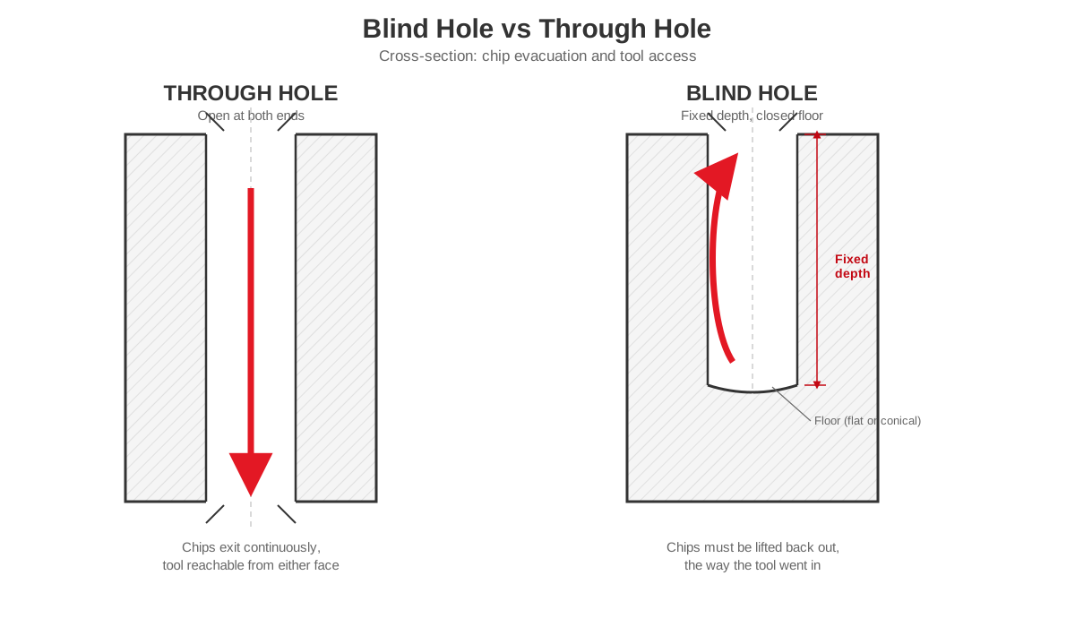
A blind hole is a hole machined to a specific depth that does not exit the opposite face of the part. It has a floor, either flat, produced with a flat-bottom end mill, or conical, left by the point of a twist drill. Light does not pass through it, and that is where the name comes from.
A through hole, by contrast, is open at both ends. A pin, a bolt, a probe or a beam of light can pass straight through it without obstruction. Every hole on a drawing is one or the other, and the distinction should be stated explicitly rather than left for a shop to infer from a section view.
Blind Hole vs Through Hole: The Core Difference
| Aspect | Through hole | Blind hole |
|---|---|---|
| Depth | Passes fully through, no separate depth callout | Fixed depth, specified apart from any thread depth |
| Floor | None, open at both ends | Flat or conical floor |
| Tool access | Reachable from both faces | Reachable from one face only |
| Chip evacuation | Chips pushed straight through and out | Chips must be lifted back out the way the tool entered |
| Inspection | Checked with a pin gauge or a direct sightline | Floor and thread depth checked without a direct line of sight |
| Typical use | Fasteners, dowels, pass-through wiring, weight reduction | Threaded mounting points, sealed assemblies, cosmetic faces |
Why a Designer Picks One Over the Other
- Assembly access. A through hole lets a bolt or dowel pass all the way and be secured from the far side. A blind hole is the right call when only one face of the part is reachable. It also works when the opposite face has to stay flat for another part to seat against it.
- Sealing. A through hole is a leak path. Any part holding fluid, gas or vacuum generally needs blind holes for its fasteners, or a through hole must be plugged after assembly.
- Weight and material. A blind hole leaves more material behind the hole than a through hole of the same depth, which matters where wall thickness or stiffness is already tight.
- Cosmetic and structural faces. A hole that stops short of an outer or finished face keeps that face intact. This matters on housings, enclosures and any part where the far side is visible or carries a load.
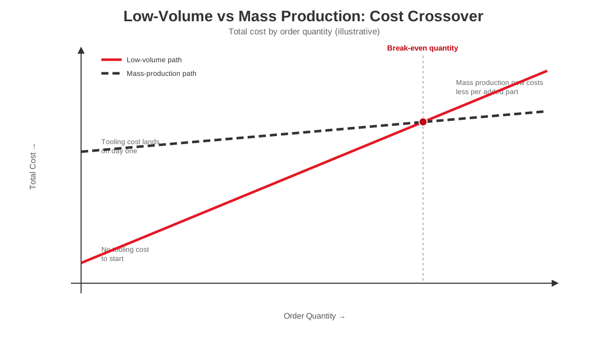
- Cost and simplicity. All else equal, a through hole is simpler and cheaper to drill and inspect than a blind hole to the same nominal depth. Blind holes earn their place when one of the reasons above actually applies to the part.
Machining Implications: Why Blind Holes Take More Care
A twist drill cuts with a pointed tip, so a blind hole drilled to a stated depth leaves a conical remainder at the floor rather than a flat one. A true flat floor needs a second operation, typically a flat-bottom end mill or a spotting pass, which adds cycle time.
Chip evacuation is the biggest practical difference between the two. In a through hole, chips are pushed straight ahead of the cutting edge and exit the far side on their own. In a blind hole they have nowhere to go but back out the way the tool went in. A through-hole tap pushes chips ahead of the cutting edge, but a bottoming tap must pull them up and out instead. Packed chips raise cutting forces, generate extra heat, and raise the odds of a broken tap or drill trapped deep in the part.
Blind hole tapping also needs careful depth control. Running a bottoming tap too far risks driving it into the floor hard enough to snap it off inside the part. That kind of break is costly to recover from. Stopping short leaves too few engaged threads to hold the fastener at full strength, so the target depth has to be set and held precisely.
Inspection is harder too. A through hole can be checked with a pin gauge or a straight sightline from either face. A blind hole cannot be sighted through. Depth, thread count and floor condition instead need a depth micrometer, a thread plug gauge or a borescope rather than a quick visual check.
Depth-to-Diameter Ratio: How Deep Is Too Deep?
Depth relative to diameter is the number that decides whether a blind hole machines cleanly or turns into a problem. General design guidance holds a drilled hole to about three times its diameter, and a bored hole to four or five times. Carbide boring bars can stretch that to about eight times in a cooperative material. Push well past those ratios and tool deflection and breakage stop being edge cases.
The same guidance recommends drilling a blind hole that will later be bored or reamed somewhat deeper than the finished depth. The extra amount, roughly a quarter of the hole's diameter, exists purely to leave room for chips to collect. That extra depth is not wasted material. It is what keeps the tool from packing solid partway down the hole.
Where a deep ratio cannot be avoided, a stepped diameter helps. Wider at the mouth and narrower toward the floor, it keeps the most fragile part of the cut as short as possible. Through holes avoid most of this risk, since chips exit continuously and the tool never works blind against a closed floor.
Threading a Blind Hole
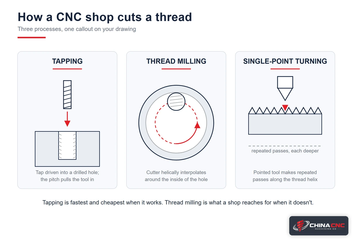
Threading adds another layer to the blind-hole question. A tapped blind hole needs its full-thread depth and total hole depth called out as two separate numbers on the drawing. Relief below the last thread should be left for chips and for the tap's lead. A shop chooses between several methods for cutting a thread: tapping, thread milling and single-point work. How each one handles a blind hole differently is covered in full in the CNC threading guide. The short version: a blind hole crowded against a shoulder, or cut in a hard material, is a common reason a shop reaches for thread milling instead of a tap.
What to Put on the Drawing
- State whether the hole is blind or through explicitly, rather than implying it through a section view alone.
- Give hole depth, and for a threaded hole, full-thread depth as its own separate number.
- Note the floor condition: flat, conical, or no requirement either way.
- Flag diameter and depth-to-diameter ratio, especially once it runs past roughly 3:1.
- Add a tolerance on depth wherever a mating part depends on it.
Getting the blind-versus-through call right on the drawing saves a round trip with the shop later. Milling covers most blind-hole and through-hole work in a single setup, and more demanding hole patterns, including deep or tightly toleranced blind holes, fall under complex capabilities. A model with holes marked blind or through, and depths called out clearly, heads off the kind of assumption that turns into a re-quote later.
Send the drawing through for a manufacturability check before committing to a final revision — get a manufacturability check.
Frequently Asked Questions
What is the difference between a blind hole and a through hole?
A through hole passes completely through the part and is open at both ends. A blind hole stops at a set depth inside the material and has a floor, either flat or conical. The difference affects chip evacuation, tool access, tapping method and how the hole gets inspected afterward.
What is the difference between a through hole and a blind hole?
The two names describe the same distinction from opposite sides. A through hole has no floor and lets a tool, pin or fastener pass all the way through. A blind hole has a closed floor, so the tool works from one direction only and chips have to be lifted back out rather than pushed through.
How deep should a blind hole be for tapping?
Call out full-thread depth and total hole depth as two separate numbers. Drill the hole a little deeper than the last full thread to leave room for chips and the tap's lead. As a general guide, keeping a drilled hole within about three times its diameter keeps tool deflection and breakage manageable. Deeper ratios call for more caution, and sometimes a different process, such as thread milling.