
Aluminum CNC Machining in China — Milling, Turning and Anodized Alloy Parts
At our Shenzhen facility we run aluminum CNC machining China programs for brackets, housings, heat sinks, and structural parts. We focus on 6061, 7075, and 5052 when your drawing defines strength, finish, and corrosion needs. Work runs under ISO 9001:2015 controls; each quote states alloy, tolerance band, and finishing so procurement sees the same scope as production.
- Precision milling and turning paths aligned to alloy and temper
- Lightweight anodized aluminum components when your spec includes coating
- DFM on thin walls, pockets, and threads before machining starts
- Inspection and documentation aligned to your incoming QC plan
How We Machine Aluminum Day to Day
Cutters follow programmed paths on mills for prismatic work, on lathes for round features, and through drill-and-tap cycles when holes and threads belong in the same setup. Aluminum sheds heat quickly and usually cuts with lower forces than many steels, so it stays a first choice for strong, lightweight parts—when the design still allows rigid fixturing and reliable chip evacuation.
Most specialist aluminum CNC machining projects hinge on three decisions: alloy and temper for the environment, repeatable dimensions on mating features, and a finishing plan that fits how the part was cut. We review your model and drawing together, then pick tooling and inspection steps that match the risk called out on the print.
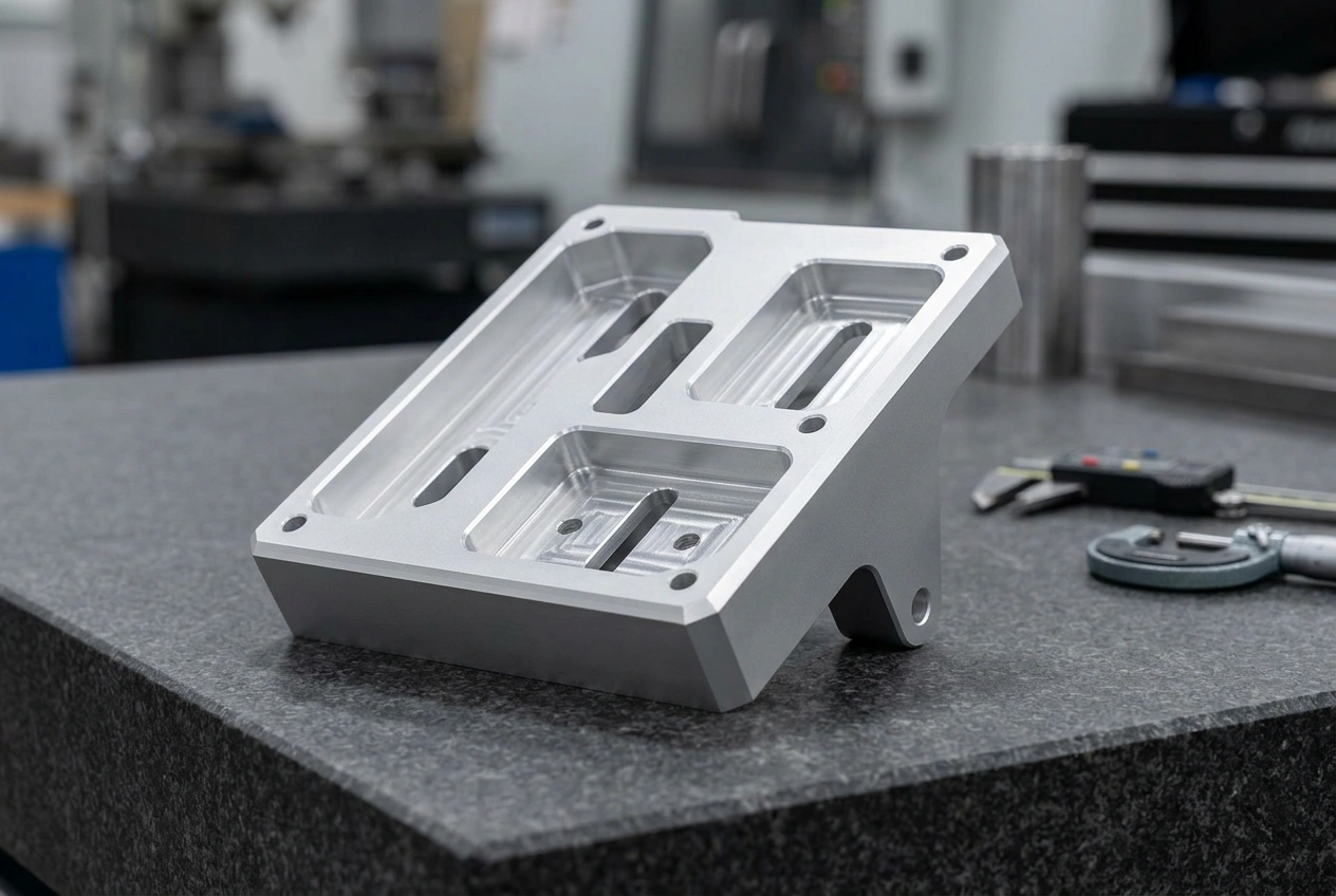
Choosing the Right Grade for Your Application
We routinely run the grades called out in your BOM—commonly 6061-T6, 7075-T6, 5052, and 2024—and document heat number or material traceability when your order requires it. The table below summarizes typical tensile strength and common uses; always confirm critical values against your material certification or standard.
Drawings reach us spelled both ways: North American prints say aluminum, prints from the UK, Europe and Australia say aluminium. Same metal, same four-digit alloy designations, same quote—we do not raise a query over it.
Name the temper, not just the alloy. The four-digit number identifies the alloying system; the suffix identifies the condition the metal is actually in. T means thermally treated—T3 is solution heat-treated then cold worked, T4 is naturally aged, T6 is artificially aged—and H means strain-hardened, so 5052-H32 is strain-hardened and then stabilized. A print that says “6061” with no temper is under-specified: 6061-O and 6061-T6 differ by roughly a factor of two and a half in tensile strength, and they do not machine, fixture or finish the same way. Our 6061 vs 7075 comparison covers strength, welding and anodizing differences in detail.
| Alloy (typical) | Approx. tensile strength (MPa) | Typical applications |
|---|---|---|
| 6061-T6 | ~310 | General brackets, frames, housings, heat sinks, weldments where 6061 is specified |
| 7075-T6 | ~572 | High-strength structural hardware, tooling plates, performance-critical parts |
| 5052-H32 / H34 | ~228 | Marine and chemical environments, sheet-style work, good formability |
| 2024-T3 / T4 | ~483 | High strength with fatigue considerations; often protected against corrosion |
For programs that combine CNC milling and CNC turning, we sequence operations so heat-treatment-sensitive features and finishing steps stay aligned with your drawing.
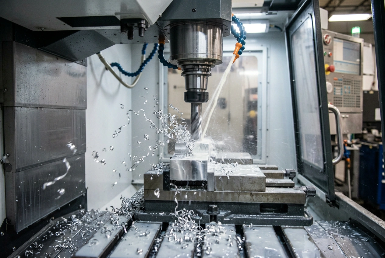
What Tolerance We Hold, and What ISO 2768 Controls
Two numbers answer most of this question. Our standard machining tolerance is ±0.05 mm, and for suitable features we hold a precision tolerance of ±0.01 mm. Which one applies is a property of the feature, not of the part: stiffness, tool access, and whether a relationship has to survive more than one setup decide it, and that is what a quote prices.
The rest of the drawing is usually covered by a general tolerance class. ISO 2768-1 exists so a drawing does not have to tolerance every dimension individually—it specifies permissible deviations for linear and angular dimensions that carry no individual tolerance indication, in four classes: f (fine), m (medium), c (coarse) and v (very coarse). It applies to parts produced by metal removal or formed from sheet metal. If it applies to yours, the standard asks that “ISO 2768” and the class—for example ISO 2768-m—be indicated in or near the title block. Marking it is what turns every unmarked dimension on the print into a defined, inspectable requirement instead of a shop assumption.
| Nominal length (mm) | f — fine | m — medium | c — coarse | v — very coarse |
|---|---|---|---|---|
| 0.5 up to 3 | ±0.05 | ±0.1 | ±0.2 | — |
| over 3 up to 6 | ±0.05 | ±0.1 | ±0.3 | ±0.5 |
| over 6 up to 30 | ±0.1 | ±0.2 | ±0.5 | ±1.0 |
| over 30 up to 120 | ±0.15 | ±0.3 | ±0.8 | ±1.5 |
| over 120 up to 400 | ±0.2 | ±0.5 | ±1.2 | ±2.5 |
| over 400 up to 1000 | ±0.3 | ±0.8 | ±2.0 | ±4.0 |
| over 1000 up to 2000 | ±0.5 | ±1.2 | ±3.0 | ±6.0 |
| over 2000 up to 4000 | — | ±2.0 | ±4.0 | ±8.0 |
Permissible deviations per ISO 2768-1, Table 1. These are the defaults that apply to dimensions carrying no individual tolerance — they describe the drawing, not a capability claim. Below 0.5 mm nominal, the standard requires the deviation to be written next to the dimension itself.
Two things follow from that table that are worth saying plainly. First, a general class is size-dependent: ISO 2768-m allows ±0.2 mm on a 20 mm feature and ±0.5 mm on a 300 mm one, so “2768-m throughout” means something different at each end of a large part. Second, the standard is explicit that a workpiece exceeding a general tolerance does not automatically get rejected if its ability to function is not impaired—which is exactly why the features that do affect function should carry their own individual tolerances rather than lean on the general class. Our ±0.05 mm standard band is tighter than ISO 2768-f from the 6 mm length band upward, and ±0.01 mm is tighter again; stating it against a published standard is what makes it checkable rather than a slogan.
Geometry has its own half of the standard. ISO 2768-2 fixes general geometrical tolerances—straightness, flatness, perpendicularity, symmetry and run-out—in three classes, H, K and L. If your print carries GD&T, say which class applies alongside the linear one.
At ±0.01 mm, the measurement conditions are part of the specification. The standard reference temperature for industrial length measurement is 20 °C. Aluminum expands about twice as much per degree as steel—roughly 23.6 µm per metre per °C against about 12 for steel—so a 100 mm aluminum bar 5 °C above reference is about 0.012 mm longer than it was at 20 °C, while a steel gauge measuring it has moved only about 0.006 mm. That difference is larger than the precision tolerance band itself. On tight-tolerance aluminum, agree the inspection temperature and the gauge material at quoting, not at goods-in. For how the same controls run across every process, see the CNC machining overview, and for a longer treatment of tolerance callouts see CNC machining tolerances explained.
How Large an Aluminum Part We Can Take
Overseas buyers ask this before they ask anything else, and most supplier pages never answer it. Ours are the two numbers below.
Fitting the envelope is the first question, not the last one. A 2 m aluminum plate that fits the table can still be the harder part to quote, because at that size the real constraints are how rigidly it can be held, how many setups the features force, and whether the datum scheme survives being re-fixtured. Large thin plate is also where locked-in stock stress shows up as bow after the first roughing pass—covered in what we watch for on aluminum below.
Three things make a large aluminum part quotable rather than risky, and all three are decided on your drawing:
- Datums chosen to match how the part is held. Good metrology practice is to pick as datum features the surfaces actually used to hold the component during manufacture, because that ties the inspection result directly to the process that produced it. On a large plate this is the difference between a part that passes and a part you argue about.
- A general tolerance class that is honest about size. Over 1000 mm, ISO 2768-m already permits ±1.2 mm — see the table above. Features that need better than that at those lengths have to be individually toleranced or they will not be held.
- A stated setup intent. Tell us which relationships must hold across setups and which do not. That single note moves more cost on a large part than the alloy choice does.
Round work is planned the same way inside the 400 mm turning envelope — see CNC turning services for the operation-level detail, and large part CNC machining for how big work is fixtured and inspected across materials.
How We Combine Mill, Lathe, and Holemaking
Milling removes material from a fixed blank to create pockets, bosses, ribs, and contoured surfaces—ideal for enclosures, plates, and manifolds. Turning is the right choice when the geometry is dominated by diameters, bores, and threads around one axis. Drilling and reaming establish hole sizes; tapping or thread milling forms internal threads per your class and gauge requirements.
When you need simultaneous multi-axis finishing on complex surfaces, we can route eligible work through our 5-axis machining capability. Not every part needs it—we quote the leanest credible process that still meets your drawing.
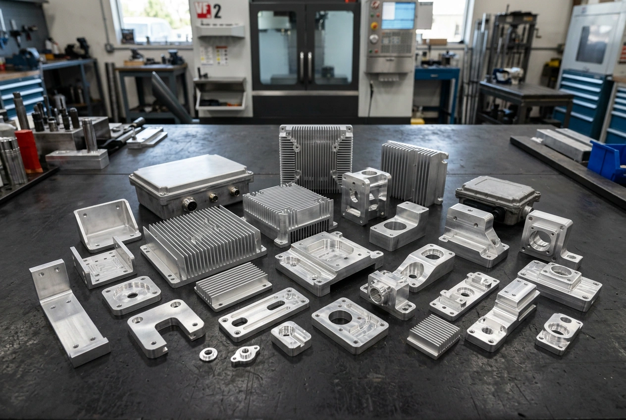
Aluminum CNC Turning and CMM-Verified QC
Round aluminum features—shafts, bushings, spindles, standoffs, and threaded connectors—run on our turning centers, sequenced with milling in the same setup when a part needs both diameters and prismatic features. Turning aluminum keeps the same alloy-and-temper planning as milling: rigid workholding, coolant matched to the cut, and tooling chosen to avoid built-up edge on soft grades.
Every turned or milled aluminum part is checked against your drawing with coordinate measuring machines and video measuring equipment, with critical diameters, concentricity, and length dimensions recorded when your order calls for a dimensional report. A dimensional report names which features were measured, against which datums, with what equipment—not a pass stamp on a page.
Turned aluminium alloy components carry the same tolerance planning as milled work: ±0.05 mm as standard, ±0.01 mm on features that justify it, and a general class from ISO 2768 covering everything the drawing leaves unmarked. Standard lead time is 10 to 15 days. The fastest we quote is 7 days, for a mini order, and that assumes the alloy is on hand and the finishing scope is simple. You receive a confirmed date during quoting rather than an open-ended promise after the PO is placed.
| Turning attribute | What we hold |
|---|---|
| Maximum turned diameter | 400 mm |
| Standard tolerance | ±0.05 mm |
| Precision tolerance | ±0.01 mm on suitable features |
| General tolerance reference | ISO 2768, class as stated on your drawing |
| Dimensional verification | CMM and video measuring equipment |
| Standard lead time | 10–15 days; 7 days at the fastest, for a mini order |
Achievable tolerance is a property of the feature, not of the material — part stiffness, tool access and setup count decide it. See CNC turning services for the full operation list.
Why Aluminum Cuts the Way It Does — With the Number
“Aluminum machines easily” is the most-repeated and least-supported sentence on supplier pages. The measurable version is specific cutting force, written kc1: the force needed to remove one square millimetre of chip cross-section. It is a property of the material group, published in the ISO 513 and VDI 3323 material-group tables that shops select grades and cutting data from, and it is roughly half for wrought aluminium what it is for plain carbon steel, and a third of what it is for annealed tool steel.
ISO 513 sorts every workpiece material into six groups — P steel, M stainless, K cast iron, N non-ferrous, S heat-resistant, H hardened. Aluminium sits in group N, defined as non-ferrous metals under about 130 HB, and the sub-group number is what actually selects the tooling.
| Material and condition | Yield strength (MPa) | Hardness (HB) | ISO 513 group | kc1 (N/mm²) |
|---|---|---|---|---|
| 6061-T6 / T651 | ~276 | ~95 | N — 22, wrought heat-treatable | 800 |
| 7075-T6 / T651 | ~503 | ~150 | N — 22, wrought heat-treatable | 800 |
| 2024-T3 | ~345 | ~120 | N — 22, wrought heat-treatable | 800 |
| 5052-H32 | ~193 | ~60 | N — 21, wrought non-heat-treatable | 700 |
| Cast aluminum, ≤12% Si | — | ~75 | N — 23 | 700 |
| Cast aluminum, >12% Si | — | ~130 | N — 25 | 750 |
| Plain carbon steel, annealed | — | 125–190 | P — 1 and 2 | 1,350–1,525 |
| High-alloy and tool steel, annealed | — | 200 | P — 10 | 2,450 |
Yield strength and Brinell hardness are typical published values for the alloy and temper; confirm critical values against your material certification. Specific cutting force and material group are from the ISO 513 / VDI 3323 material-group tables. For the same comparison from the buying side, see aluminum vs stainless steel CNC machining.
Lower force means lower power, which is why aluminum is the productive choice — when the part can be held rigidly enough to use it. On a stiff, well-supported part the low kc1 converts directly into material removal rate. On a thin web or a tall unsupported wall it does not, because the limit stops being the spindle and becomes deflection. That is the honest reason two aluminum parts of the same weight can quote very differently.
Cast aluminum is a different conversation from wrought, and the silicon content is why. Cast alloys at or below about 12% silicon behave close to wrought aluminum and take fine-grain uncoated carbide happily below roughly 7–8% Si. Above 12% Si the alloys are hypereutectic, sit in their own material group, and generally want PCD-tipped tooling and a lower speed with a heavier feed. Cast surfaces and any porosity are a drawing conversation before the first cut, not a surprise at inspection — send the casting spec with the model.
What We Watch for on Aluminum
Aluminum’s softness can encourage built-up edge—workpiece material welding itself to the cutting edge in layers, then breaking off and taking finish and dimensional repeatability with it. It forms at low cutting speeds, because a cool tool–chip interface leaves the work material strong right at the edge, and it is worst on soft, ductile alloys. The primary fix is therefore the one most pages omit: raise the cutting speed. Increasing rake angle, applying a coating or lubricant that reduces tool–chip friction, and choosing two- or three-flute end mills for slotting all help, but they are secondary to speed.
Chip evacuation matters because aluminum is a long-chipping material—readily controlled when it is properly alloyed, sticky and demanding of sharp edges when it is close to pure. Long chips wrap tools or get re-cut into the finished face. High-pressure coolant, chip-breaking strategies, and toolpaths that avoid rubbing in corners are what keep a lights-out cycle from becoming a scrapped part.
Thermal expansion is about twice steel’s—roughly 23 to 24 µm per metre per °C against about 11 to 12 for steel. On a long or thin aluminum part that is a real measurement error rather than a rounding one, which is why shop temperature and part temperature at inspection are agreed with the tolerance rather than after it.
Why a first article can pass and the tenth part not. Machining leaves residual stress in the surface, and residual stress causes distortion in thin-walled work—an old problem in airframe structure for exactly this reason. With a sharp tool those stresses do not usually reach much deeper than about 50 µm below the surface; with a worn tool they can reach five to ten times that depth. That is the mechanical reason a shop changes tooling on a schedule instead of waiting for the finish to look wrong. Plate stock carries its own locked-in stress from the mill as well, which is what the stress-relieved tempers exist for: on a machined-from-plate 7075 or 2024 part, calling T651 or T7351 on the drawing rather than plain T6 changes how the part behaves after roughing, and it is your decision, not ours.
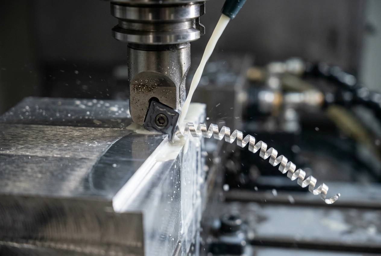
Quality System Built on ISO 9001:2015
Our quality system is built around ISO 9001:2015 controls: documented processes, trained operators, and calibration discipline on metrology equipment. Alongside it we hold ISO 14001 for environmental management, ISO 13485 for medical device quality management, and IATF 16949 for automotive quality management—so a buyer in either of those sectors is not asking us to build a system from scratch for their programme.
Where your drawing calls for first-article inspection (FAI) or production sampling, we align CMM, height gauges, thread gauges, and surface checks to the features you care about—not a generic checklist. A dimensional report states what was measured, against which datums, with what equipment, and at what temperature; on tight-tolerance aluminum the last of those is not a formality.
Material certificates and traceability can be provided when specified at order entry so your records match incoming inspection requirements.
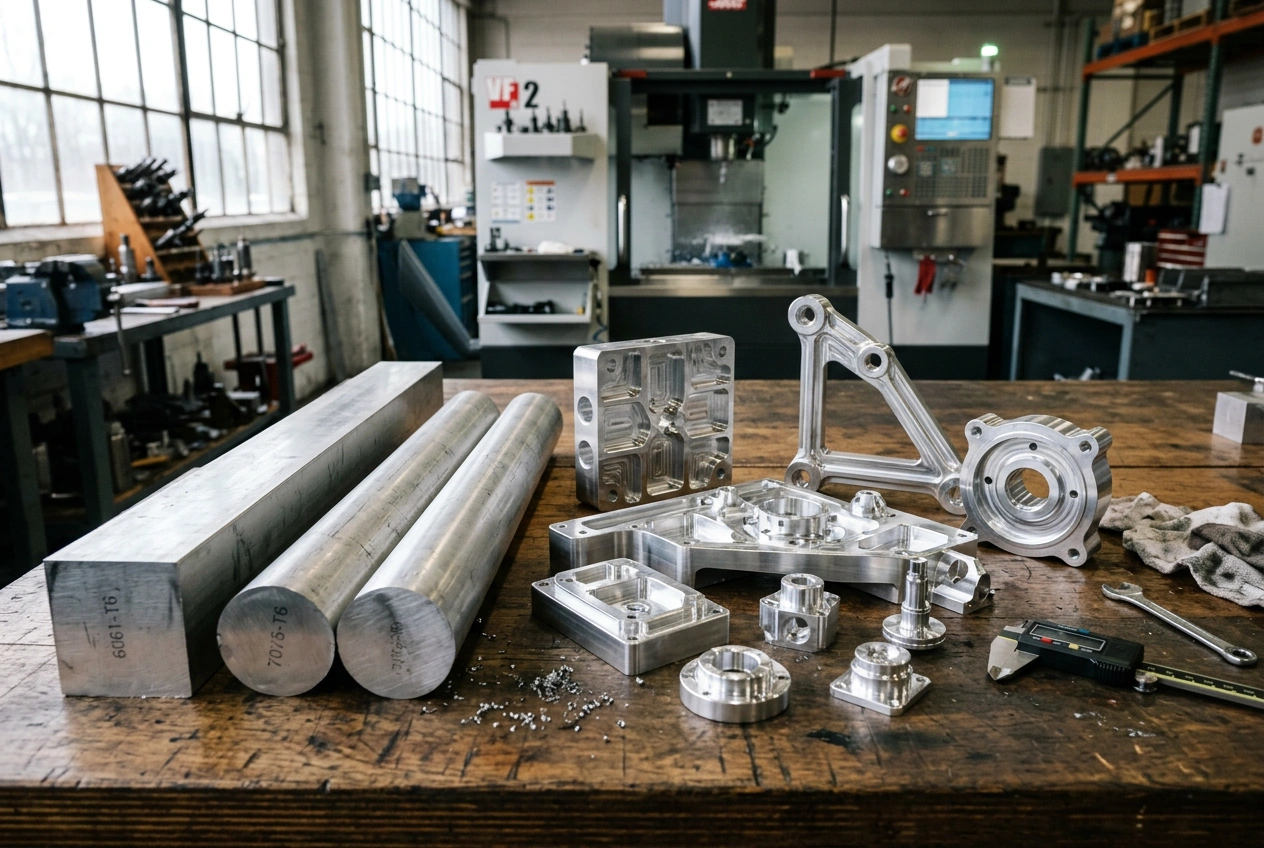
Finishes After the Chips Stop
Anodizing grows a controlled oxide layer that improves corrosion resistance and wear on many aluminum alloys; decorative and hard-coat variants are specified by thickness, color, and seal. Conversion coatings and passivation may apply depending on alloy and end use. Powder coating and bead blast adjust appearance and texture—each step needs edge breaks and masking discipline so coatings adhere without masking critical mates.
We coordinate with finishing partners when your PO includes post-processing, and we machine lightweight anodized aluminum components with the cosmetic stock and deburr strategy your finisher expects. For a fuller list of coatings and prep, see surface finishing; for how services fit together, see the CNC machining overview.
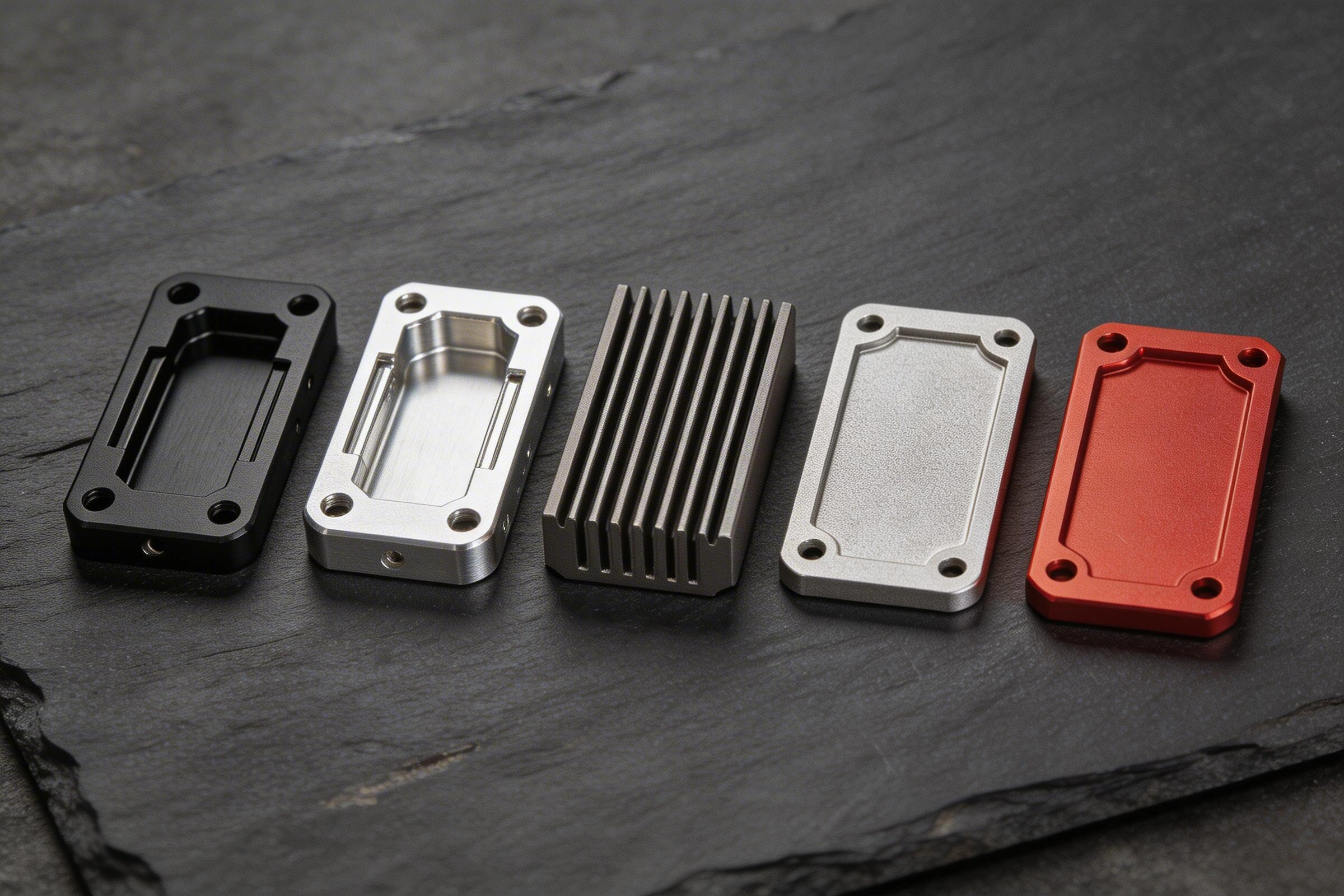
What Anodizing Does to Your Dimensions
“Anodized” is not a specification. The one buyers and shops both work from is MIL-A-8625, which covers six types and two classes of anodic coating on aluminum. Three of them account for nearly everything that arrives here: Type I chromic acid, Type II sulfuric acid—with Type IIB as the non-chromate alternative to Type I—and Type III hard anodize, defined in the spec as a heavy dense coating of specified thickness. Classes are simpler: Class 1 is non-dyed, Class 2 is dyed. Heat-treatable alloys are anodized in their final temper.
| Coating | MIL-A-8625 type | Thickness range (in) | Approx. thickness (µm) | Dimensional build-up |
|---|---|---|---|---|
| Chromic acid | Type I / IB | 0.00002 – 0.0003 | ~0.5 – 7.6 | Negligible |
| Sulfuric acid | Type II / IIB | 0.00007 – 0.0010 | ~1.8 – 25 | About half the coating thickness |
| Hard anodize | Type III | 0.0005 – 0.0045 (nominal 0.002) | ~13 – 114 (nominal ~50) | About half the coating thickness |
Thickness ranges are the inch values given in the specification; micrometre figures are arithmetic conversions and are approximate. Unless a contract says otherwise, Type III nominal thickness is 2 mil (about 50 µm).
Here is the part almost nobody publishes: the coating grows in both directions. Roughly half of an anodic coating penetrates the part and half stands proud of it, so dimensional build-up is about half the coating thickness. A 2 mil (0.002 in) hardcoat penetrates 0.001 in and protrudes 0.001 in, which means a Ø1.000 in machined feature finishes at Ø1.002 in. All machining is completed before anodizing, so on close-tolerance features that allowance has to be planned into the programmed size—before the part is cut, not after it comes back from the finisher.
Hard anodize also needs an edge radius. The coating cannot form properly over a sharp corner, and the specification gives the minimum radius against nominal thickness:
| Nominal coating thickness (in) | Radius on edges and inside corners | Approx. (mm) |
|---|---|---|
| 0.001 | approximately 1/32 in | ~0.8 |
| 0.002 | approximately 1/16 in | ~1.6 |
| 0.003 | approximately 3/32 in | ~2.4 |
| 0.004 | approximately 1/8 in | ~3.2 |
Three more decisions belong on the drawing rather than in an email after the fact:
- Blind holes and crevices. Sulfuric anodizing risks trapping electrolyte in blind holes, joints and pores. Where entrapment is likely, chromic (Type I) is the coating that gets specified. Weep holes and avoiding blind features are the design answer.
- Alloy chemistry limits Type III. Unless the contract, order or drawing says otherwise, Type III coatings are not applied to alloys with nominal copper above 5.0% or nominal silicon above 8.0%. If your alloy is near either line, raise it at RFQ.
- Anodizing makes welds conspicuous. On a 6061 weldment that is a cosmetic outcome to agree in advance, not a defect to discover at goods-in.
We machine to the finisher's requirement rather than handing the problem downstream—cosmetic stock, edge breaks, masking of critical mates, and racking-friendly geometry are planned with the routing. For the full coating and prep list, see surface finishing.
Industries That Rely on Machined Aluminum
Heat sinks and enclosures for electronics, brackets and fixtures for industrial equipment, automotive adapters and test hardware, medical device components, and broader OEM assemblies where weight and corrosion drive the design. Our certified scope is ISO 9001:2015, ISO 14001, ISO 13485 and IATF 16949. If your programme requires a certification outside that list—including on aerospace work—tell us at RFQ and we will say plainly whether we hold it rather than let a scope gap surface at audit.
Prototype quantities or recurring releases both start with the same step: agree inspection and finishing scope before metal is cut.
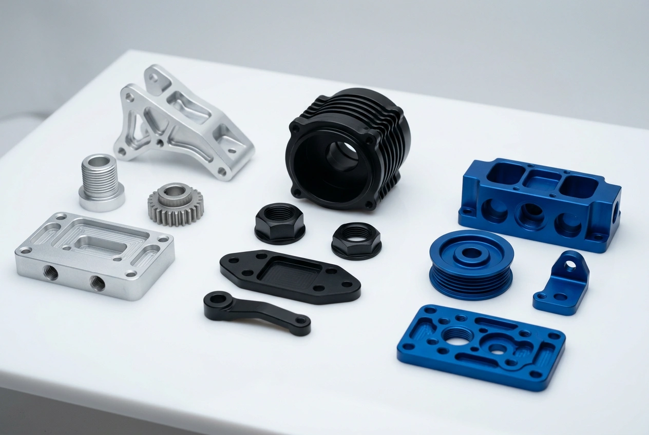
What Sets Our Aluminum Work Apart
The alloy is easy to source; the difference is how we plan tooling, fixturing, and inspection around your actual print.
Alloy-First Planning
Mills and lathes tuned to the grade you actually buy—not a generic “aluminum” recipe.
Chip and Heat Control
Tooling and coolant strategies that reduce built-up edge and re-cutting on soft alloys.
Metrology Matched to Risk
Critical dimensions get planned checks—CMM or manual—per your drawing.
Export-Ready Delivery
Packing and documentation for buyers in North America, Europe, and Australia.
Questions About Aluminum CNC Machining
Why choose CNC machining for aluminum parts?
CNC machining removes material under program control, so complex pockets, bores, and contoured surfaces repeat from the first piece to production lots. Aluminum’s high machinability usually allows productive feeds and speeds when tooling and coolant are matched to the alloy—making CNC a practical path for brackets, housings, heat sinks, and structural parts where drawings define critical dimensions and finishes.
6061 vs 7075 vs 5052—which aluminum should I specify?
6061-T6 is a common general-purpose choice: good strength, corrosion resistance, and weldability for many brackets and frames. 7075-T6 offers higher strength for weight-sensitive structures but is less forgiving for certain welding scenarios—often seen in performance hardware. 5052 is work-hardened, non-heat-treatable sheet/plate material with excellent corrosion resistance and formability—common in marine and chemical environments. 2024 is high strength with fatigue resistance in some aircraft-style applications but is more corrosion-sensitive without protection. We align grade to your environment, loads, and finishing plan.
Is aluminum easier to machine than steel?
Generally yes, and there is a number behind it. Specific cutting force—the force needed to remove one square millimetre of chip cross-section—is about 700 N/mm² for non-heat-treatable wrought aluminum and about 800 N/mm² for heat-treatable grades such as 6061, 7075 and 2024, against roughly 1,350 to 1,525 N/mm² for annealed plain carbon steel and about 2,450 N/mm² for annealed high-alloy and tool steel. Lower force means lower power and higher removal rates, so aluminum is usually more productive per spindle hour. “Easy” does not mean careless: soft alloys weld to the tool as built-up edge at low cutting speeds, produce long stringy chips, and move thermally during long cycles. The commercial point is that tolerance band and finishing scope move a price more than the alloy does.
What tolerances can you hold on machined aluminum?
Our standard machining tolerance is ±0.05 mm, and for suitable features we hold a precision tolerance of ±0.01 mm. Which one applies depends on part stiffness, feature accessibility, and whether a relationship has to hold across setups—not on aluminum alone—so we quote tolerance bands against the actual geometry rather than publishing one number for everything. Dimensions the drawing leaves unmarked are usually covered by a general tolerance class from ISO 2768-1, in classes f, m, c or v; mark the class in or near your title block and every unmarked dimension becomes a defined, inspectable requirement. ISO 2768-2 does the same job for geometry in classes H, K and L. Call out critical dimensions and datums so inspection matches how you approve parts.
Can you supply anodizing or other finishes after machining?
Yes, subject to your specification. Decorative and hard anodize, conversion coatings, passivation for compatible alloys, powder coating, bead blast, and film-adhesive prep are common follow-ons. We coordinate cosmetic stock, edge breaks, and racking-friendly geometry so secondary processing does not undo machined dimensions.
What should I upload for an aluminum machining quote?
Send a solid model (STEP, STP, IGES, or X_T) plus a PDF or DWG drawing when you have GD&T, threads, surface finish, or notes not fully captured in the solid. Include alloy and temper, quantity, finishing scope, and any inspection or material certification requirements so the quote covers the same scope as production.
How does lot size affect aluminum CNC pricing?
Prototype and low-volume runs absorb more engineering and setup per piece; higher volumes amortize fixturing and programming across more units. Material grade, tolerance bands, and finishing also move price more than alloy choice alone. We quote setup, cycle risk, and inspection explicitly so the unit economics match your stage—prototype, bridge, or recurring production.
How fast can you deliver machined aluminum prototypes or production lots?
Standard lead time on aluminum CNC work is 10 to 15 days. The fastest we quote is 7 days, for a mini order, and that assumes the alloy is on hand, the programming is straightforward and the finishing scope is simple. Where a part sits inside that range depends on material availability, programming complexity, finishing scope and inspection level. First articles usually move in the shorter part of the window once alloy, tooling and gauging are agreed. You receive a confirmed date during quoting rather than an open-ended promise after the PO is placed.
Do you CNC turn aluminum parts, and how is quality verified?
Yes—shafts, bushings, spindles, and other round aluminum features run on our turning centers alongside milled work, with lathe-and-mill sequencing planned in the same setup when a part needs both. Turned aluminum is checked with CMM and video measuring equipment against your drawing's critical diameters, concentricity, and length callouts, with dimensional records available when your order specifies them.
How large an aluminum part can you machine?
CNC milling within 3000 mm long, and CNC turning within 400 mm diameter. Fitting the envelope is the first question rather than the last one, though: at that size the constraints that decide whether a part is quotable are how rigidly it can be held, how many setups the features force, and whether the datum scheme survives being re-fixtured. Choosing as datums the surfaces actually used to hold the part in manufacture ties the inspection result to the process that produced it, which matters far more on a large plate than on a small housing. Note also that a general tolerance class gets looser with size—over 1000 mm, ISO 2768-m already permits ±1.2 mm—so features needing better than that at those lengths have to be individually toleranced.
Does anodizing change my part’s dimensions?
Yes, and it is the anodizing question that costs buyers the most money. Roughly half of an anodic coating grows into the part and half stands proud of it, so dimensional build-up is about half the coating thickness. A 2 mil (0.002 inch) hardcoat penetrates 0.001 inch and protrudes 0.001 inch, so a 1.000 inch diameter machined feature finishes at 1.002 inch. All machining is completed before anodizing, so on close-tolerance features that allowance is planned into the programmed size in advance. Hard anodize (MIL-A-8625 Type III) also needs an edge radius—approximately 1/16 inch for a 0.002 inch coating—so a hard-anodized part drawn with sharp corners will not come back the way it was drawn. Tell us the type, class and thickness at RFQ and the machining allowance is built in.
How thin a wall can you machine in aluminum?
The honest answer is that it is set by the geometry rather than by a single number, and the mechanism is worth understanding before you commit the design. Machining leaves residual stress in the surface, and residual stress causes distortion in thin-walled work—a long-standing problem in airframe structure for exactly this reason. With a sharp tool those stresses do not usually reach deeper than about 50 micrometres below the surface; with a worn tool they can reach five to ten times that depth, which is why tooling gets changed on a schedule rather than when the finish starts to look wrong. Plate stock also carries locked-in stress from the mill, which is what the stress-relieved tempers such as T651 and T7351 exist for. Send the model with the height-to-thickness ratios you need and we will tell you what is realistic before anything is programmed.
Do you machine cast aluminum as well as wrought?
Yes, and the silicon content is what changes the plan. Cast alloys at or below about 12% silicon behave close to wrought aluminum and take fine-grain uncoated carbide happily below roughly 7 to 8% silicon. Above 12% silicon the alloys are hypereutectic, sit in their own ISO 513 material group, and generally want PCD-tipped tooling with a lower speed and a heavier feed. Cast surfaces and any porosity are a conversation to have on the drawing before the first cut rather than a surprise at inspection, so send the casting specification along with the model and the machining drawing.
Which quality certifications do you hold?
Our certified scope is ISO 9001:2015 for quality management, ISO 14001 for environmental management, ISO 13485 for medical device quality management, and IATF 16949 for automotive quality management. Certificates are available on request at order entry, alongside material certificates and traceability when your incoming inspection requires them. If your programme needs a certification outside that list, tell us at RFQ and we will say plainly whether we hold it rather than let a scope gap surface at audit.
Request a quote on aluminum CNC parts
Send CAD and drawings for 6061, 7075, 5052, or another specified grade. We return lead time, finishing options, and inspection scope in writing.
Why buyers choose us
- 12–24h quote turnaroundPricing, lead time, and DFM feedback — fast.
- NDA-ready & confidentialYour CAD files and IP stay protected.
- ISO 9001:2015 certifiedDocumented inspection at every stage.
- No fixed MOQFrom single prototypes to full production runs.